
Getting ESP-IDF working with Arduino
Preliminaries
This will be the first part in a series of posts on building a DIY Bluetooth audio receiver. Getting a clock generator working is an essential component of that project, since the Digital to Analog Converter (DAC) that makes up part of the receiver needs a steady clock signal to derive the frequency of other signals, such as the sample rate (44.1 khz usually).
How to use Arduino code alongside ESP-IDF
The Espressif docs have general instructions on setting up Arduino as an ESP-IDF component which I would recommend reading first before this post.
This guide will cover some details that the official docs leave out on how to combine ESP-IDF and Arduino based code into one project. Generally, you would use one or the other, but in some cases it makes sense to combine both into a single project.
I will also use an example project that generates a clock signal on the Si5351 clock generator, using an Arduino library created by Adafruit. There are tons of great and useful Arduino libraries, and useful APIs from ESP-IDF, so this shows you how to combine them!
The steps to actually get something working are a bit tedious, but as it stands there is no other way short of porting Arduino code to ESP-IDF.
Getting the right versions of ESP-IDF and the Arduino library checked out
First of all, you must set up ESP-IDF on a specific commit in the git history, as well as a specific commit in the arduino component. If you do not do this, your code will fail to compile, since the Arduino component is only tested against specific releases of the ESP-IDF SDK.
You can find specific information about which commits to use in this file
For example, at the time of writing this the file contains these lines:
esp-idf: v4.4.3 6407ecb3f8
arduino: master 947ee6fd
esp-dl: master f3006d7
esp-dsp: master 8e5e9f6
esp-insights: main 94f929d
esp-rainmaker: master fe94cc6
esp-sr: master 7154450
esp32-camera: master 402b811
esp_littlefs: master f2a949f
tinyusb: master 97984b420
Therefore I will be on commit 6407ecb3f8d2cc07c4c230e7e64f2046af5c86f7 for esp-idf, and on 947ee6fd for arduino (or any later or earlier commit that has the same corresponding esp-idf version).
So you would do git checkout 6407ecb3f8d2cc07c4c230e7e64f2046af5c86f7 or git checkout v4.4.3 to get to that specific commit on ESP-IDF, then do the same with the arduino component after cloning it to yourproject/components/arduino. If you have already set up ESP-IDF, I recommend setting everything up from scratch again. You could also have multiple ESP-IDF versions checked out in different locations. The official documentation has more details in the getting started section, which you can find here.
My example project already has all of this setup for you except esp-idf itself.
Example project
For this guide, you can just clone my project to any directory and run the following command
source $HOME/esp/esp-idf/export.sh
This will allow you to call idf.py.
Verify that you have the correct versions of everything before moving on to the next step. Remember that you must have esp-idf checked out to a specific commit.
Then you will create a sample project, and create a components directory with the right arduino component checked out.
As mentioned, I've already created a project which has all of the files needed.
Here are the commands you need to run, assuming you have setup esp-idf and your current working directory is where you'd like to have projects stored:
git clone --recurse-submodules https://github.com/weskerfoot/clock_example
cd clock_example
idf.py menuconfig # only run if you want to change the settings
idf.py build && idf.py -p /dev/ttyUSB0 && idf.py monitor
The first command should check out the project, including everything in the submodule as well. Then you will build the project and flash it, then monitor it over the serial connection provided by the USB port on your dev board. Any error messages will cause the step after to not run. You will have to troubleshoot any issues at that point.
It is important that you also have CONFIG_FREERTOS_HZ=1000 in your sdkconfig file as well, which should be set on my repo by default. This setting is required by the Arduino library. You will get an error from idf.py build if you don't have it set properly.
The code that glues everything together is located in clock.cpp and it's quite simple.:
extern "C"
void
setupClock() {
  ESP_LOGI("setupClock", "setupClock being called");
  initArduino();
  ESP_LOGI("setupClock", "arduino initialized");

  Adafruit_SI5351 clockgen = Adafruit_SI5351();

  ESP_LOGI("setupClock", "class initialized");

  ESP_LOGI("setupClock", "setClockBuilderData called");

  if (clockgen.begin() != ERROR_NONE) {
    ESP_LOGI("setupClock", "clockgen.begin ERROR!! XXX");
    while(1);
  }
  ESP_LOGI("setupClock", "clockgen.begin called without errors");

  clockgen.setupPLL(SI5351_PLL_A, 35, 3493, 15625);

  ESP_LOGI("setupClock", "SHOULD be at 11.28 mhz");

  clockgen.setupMultisynth(0, SI5351_PLL_A, 78, 0, 1);

  clockgen.enableOutputs(true);
}
Firstly, you must have extern "C" before your function declaration, or else the compiler will not compile it using the C calling convention, which means it cannot be called from C code. If your entire project is in C++, then you should leave it out, but in this example we are assuming it will be called from a C file. You can wrap any function this way pretty much.
the initArduino function must be called once at the start, therefore you should only need to call this function once inside the app_main entrypoint. The rest of the code just uses the clock library to setup the PLL and divider which you can read more about at the Adafruit docs. It also contains some logging functions which come from the "esp32-hal-log.h" file.
Once you build and flash this using the aforementioned commands, you should see an 11.2891 MHz signal on the outputs of the device. You can create any signal you want within the range of the board, from 8 kHz to 160 MHz according to the datasheet. Make sure to follow the guidelines on selecting optimal values for the PLL and divider, which the Adafruit guide has more information on.
In this example, I ran the following frequency plan using the ClockBuilder software which I ran under WINE since I use Linux and it's a Windows program.
I get the following output from the software
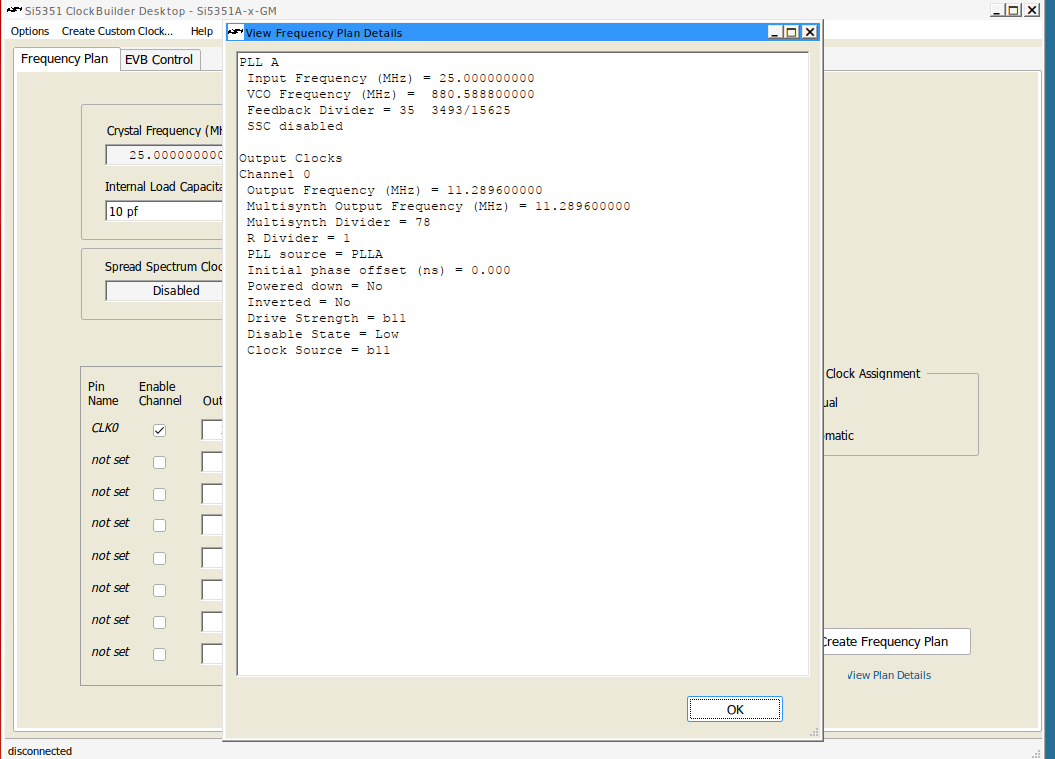
Which corresponds to this formula (25 * (mult + num/denom)) / divider, which gives this expression when the values are plugged in, (25 * (35 + (3493/15625))) / 78 which gives 11.2896. This is approximately close to what is actually measured. If you want more accurate output you can use integer mode but you are more limited in which frequencies you can generate.
Setting up the hardware
The setup is very simple. Just connect your 3v and GND pins to the corresponding pins on the Si5351, then connect pin 21 to SDA and pin 22 to SCL, and solder a wire to the corresponding channel output (in this example channel 0), which you can use to test the clock signal or connect it to another component such as a DAC, which needs a reference clock.
Here is the signal as it appears on an oscilloscope.
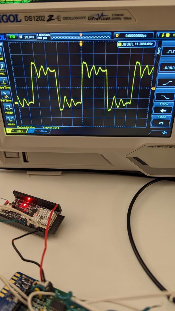
And the physical wiring.

If you have any issues, please file them on the Github repo and thanks for reading!